Every since discovering the Amstrad CPC one quirk of it’s hardware has been disturbing my enjoyment of demos on this platform.
The CRTC differences.
In the beginning most Amstrad CPC’s shipped with a CRTC0, as such most demo-makers discovered its hardware capabilities and
based their routines on it.
But it became apparant that different CRTC chips were used during the lifespan of the Amstrad CPC.
As can be found in this OVERVIEW
So while demo-makers have adapted their code to run on several different types some hardware tricks are only possible on a specific type.
Both my 464 and 6128 have a CRTC type 1 which isn’t too bad since some demos have now been made exclusively for this CRT type but well
some simply don’t work since they expect a CRTC type 0.
I was unable to find a good source of CRTC type 0 until I found a Youtube repair video,
based off that the person in the video lives in Austria, I went ahead and asked if they could provide me their eBay seller since I presumed it would be an European seller.
The eBAY seller was located in Poland so no import fees and a good price.
My order was placed for 4 x CRTC type 1 aka the Hitachi HD6845S, which apparantly can be found in videorecorders and such.
Once they arrived I delved into the details of this article on how to do a dual-CRTC piggybanking setup.
You basically take pin 20 of the CRTCs, which is VCC (5V), disconnect it and run a wire from the PCB to a switch and both pin 20ies of the
CRTCs to that same switch.
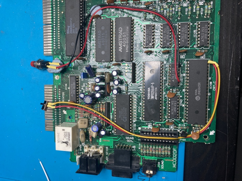
First ,the 464.
This one is a pretty simple one since all components are spread on the motherboard so there is enough room to get to the CRTC with a
soldering iron.
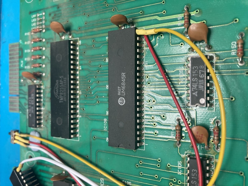
Here is the original UM CRTC1 chip with all the wiring done.
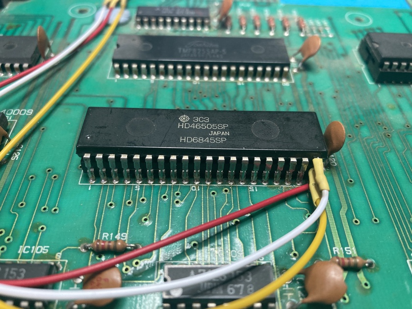
A view of the new Hitachi CRTC0 before stacking it on top of the other one.
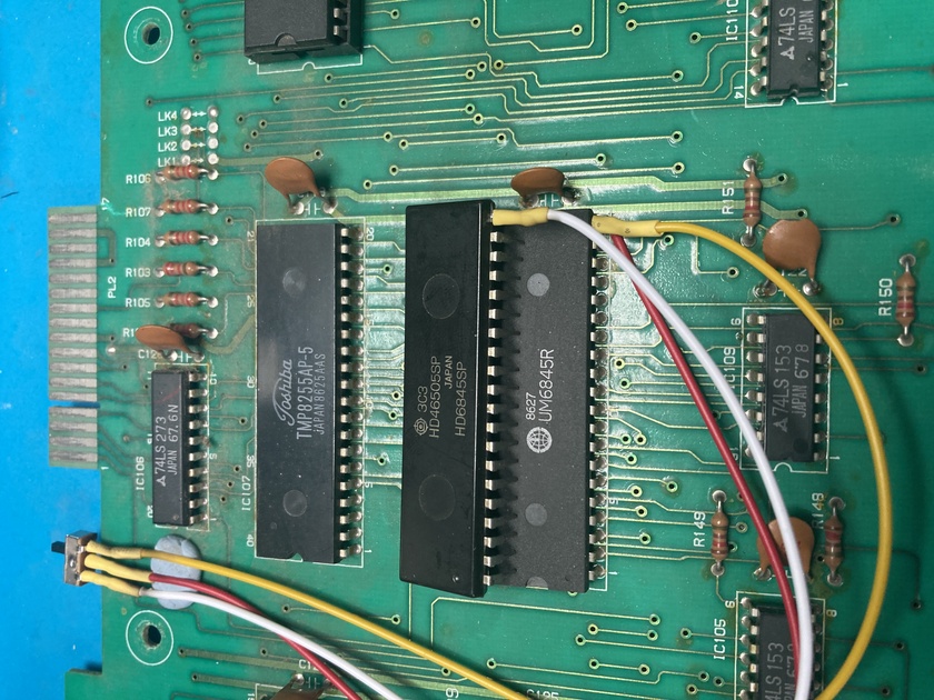
Piggyback, now to solder the remaining pins of the 2 CRTCs together.
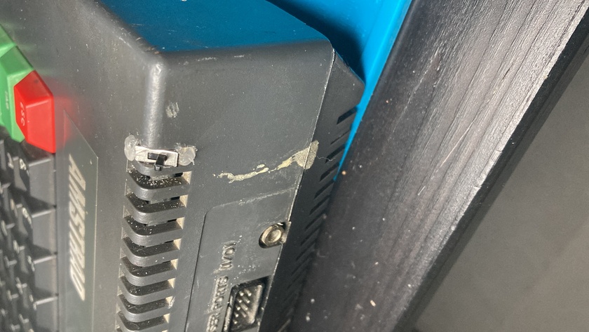
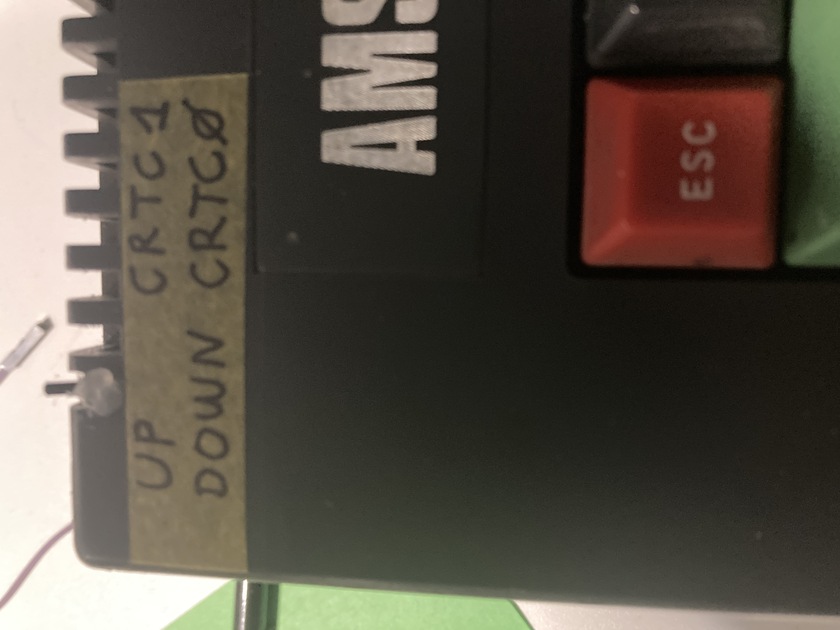
I enlarged the venting hole in the top left corner of the 464 with a file to fit the switch.
And made a note on paper tape which was which.
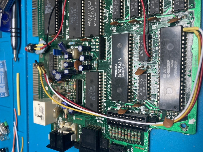
The 6128 is bit more difficult to solder since the CRTC sits in the
bottom right corner and there is not a lot of room around it but
after a failed attempt , I started again in the morning with a fresh
view on things and succeeded.
First the wiring of the original UM CRTC1 towards the toggle switch.
And then stacking the new Hitachi CRTC1 on top of it.
Since I didn’t want to damage the case too much , I found that the
switch could sit perfectly between the TAPE and the JOYSTICK port on
the left side of the 6128.
So I only had to break of a tiny part of the case and hotglue the switch into place.
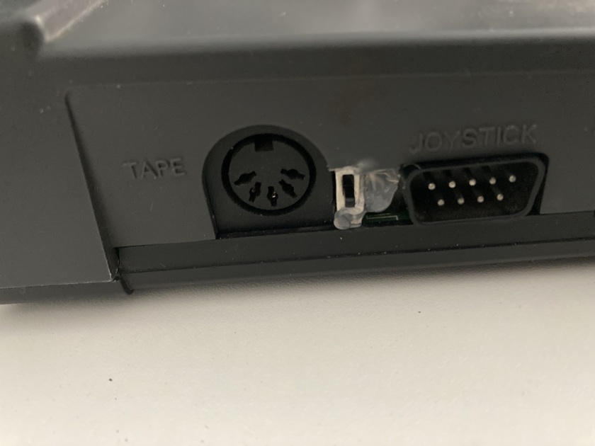
You wouldn’t know that the switch was there if you weren’t told.
And as such my CPC’s can now enjoy the best of both worlds.
Or better said I can finally see the Borderline Demo released at Benediction Coding Party 4 wich only runs on CRTC type 0 , 3 and 4.
BORDERLINE
The authors did however include an easter egg for those running it with the wrong CRTC.
BORDERLINE_WRONG_CRTC
Which is ideal for me to test my switch setup :)